
General Introduction
The energy metering devices record active and reactive energy consumption. The electricity suppliers generally show the term tan or cos on their bill. Unlike the cos , it is easy to see that the value of tan should be as small as possible in order to have the least reactive energy consumption.
Reactive power compensation gives you the following benefits:
• Savings on electrical equipment, a decrease of the power demand.
• An increase in available power of the supply transformer.
• Lower voltage drops and Watt losses in cables.
• Savings on electricity bills by eliminating reactive energy consumption.
• The reduction of subscribed power KVA (if available)
To compensate for reactive power, it is necessary to provide reactive power by installing compensation equipments instead of taking it from the main distribution. If the value of reactive power to compensate it is small compared to the total apparent power of all the loads (Qc/St<15%), we can choose fixed type compensation equipment. If this value is higher (Qc/St>15%), it is advisable to choose an automatic compensation equipment.
Application & Features
These capacitors are suitable for Three phase power Factor correction where there is Dynamic fluctuation of the load and system Voltage variation is around 20%.
Features of the capacitor:
- Manufactured by using imported hazy BOPP film as main dielectric
- High purity (>99%) Aluminium Foil used as Electrode for high current inrush
- Internal fuse to each element is possible for better safety
- Robust & Highly reliable capacitor performance
- Guaranteed output for a longer period i.e. 10-15 years
Types
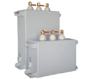
APP Capacitor Units
^ top
These capacitors are available in both cylindrical and box type variants and are mostly used for fixed or automatic compensation of light loads.
Specifications:
| Range | 5-50 KVAR |
| Type | APP type - Ultra Heavy Duty |
| Standard | IS 13585-1994,IEC 60931-2002 |
| Rated Voltage | 415-1000 Volts |
| Rated Frequency | 50/ 60 Hz |
| Over Current | 3.0 x I n |
| Inrush Current | 500 x In |
| Operating Losses (Dielectric) | < 0.2 W / KVAR |
| Operating Losses (Total) | < 0.5 W / KVAR |
| Capacitance Tolerance | 0% To +10% |
| Protection Class/Type | IP52 with terminal cap |
| Temperature Category | -25° to 70°C |
| Discharge Resistor | Special Design Internal Discharge.Resistance 50 V In Less Than 60 Sec |
| Cooling | Natural or forced air cooling |
| Safety Features | Internal Fuse |
| Test Voltage Terminal to Casing | U≤ 660 V: 3000V AC 10 Sec, U = 660 V :6000V AC 10 Sec |
| Impregnation | Non PCB, Biodegradable Oil |
| Casing | Sheet Steel |
| Terminals | Porcelain Bushing |
| Discharge Resistors / Time | Discharge Resistors fitted,Standard discharge time 60seconds, Other discharge times on request |
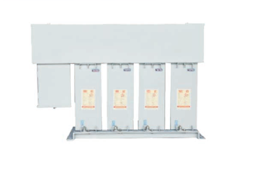
APP Capacitor Banks
^ top
Banked units proviing KVAR outputs over 50 KVAR with terminal cover. Banking can be done using Al or Cu bus bars as required. Optional incoming protection using HRC fuses or MCCB.
Specifications:
| Range | 50-500 KVAR |
| Type | APP type - Ultra Heavy Duty |
| Standard | IS 13585-1994,IEC 60931-2002 |
| Rated Voltage | 415-1000 Volts |
| Rated Frequency | 50/ 60 Hz |
| Over Current | 3.0 x I n |
| Inrush Current | 500 x In |
| Operating Losses (Dielectric) | < 0.2 W / KVAR |
| Operating Losses (Total) | < 0.5 W / KVAR |
| Capacitance Tolerance | 0% To +10% |
| Protection Class/Type | IP52 with terminal cap |
| Temperature Category | -25° to 70°C |
| Discharge Resistor | Special Design Internal Discharge.Resistance 50 V In Less Than 60 Sec |
| Cooling | Natural or forced air cooling |
| Safety Features | Internal Fuse |
| Test Voltage Terminal to Casing | U≤ 660 V: 3000V AC 10 Sec, U = 660 V :6000V AC 10 Sec |
| Impregnation | Non PCB, Biodegradable Oil |
| Casing | Sheet Steel |
| Terminals | Porcelain Bushing |
| Discharge Resistors / Time | Discharge Resistors fitted,Standard discharge time 60seconds, Other discharge times on request |